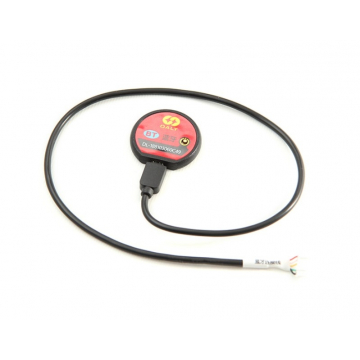
- Bluetooth


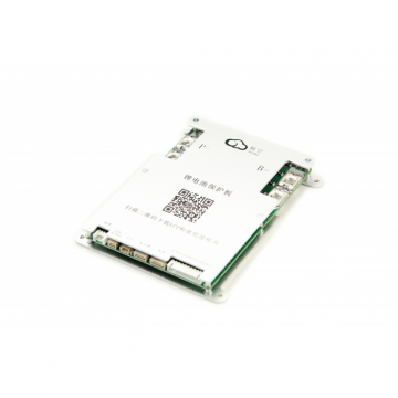
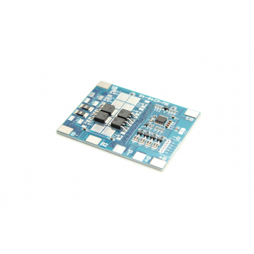
Device - DALY SMART Balancer Active 8S for balancing cell voltage and monitoring energy transfer among them.
ATTENTION! THIS BALANCER HAS NO BMS FUNCTION. THIS PRODUCT ONLY EXTENDS THE FUNCTIONALITY OF CURRENT BMS.
*Product photo is illustrative
Lowest price in the last 30 days before discount 999 Kč
![]() DOCUMENTS FOR DOWNLOAD
DOCUMENTS FOR DOWNLOAD
Read more: how pre-orders work

Features
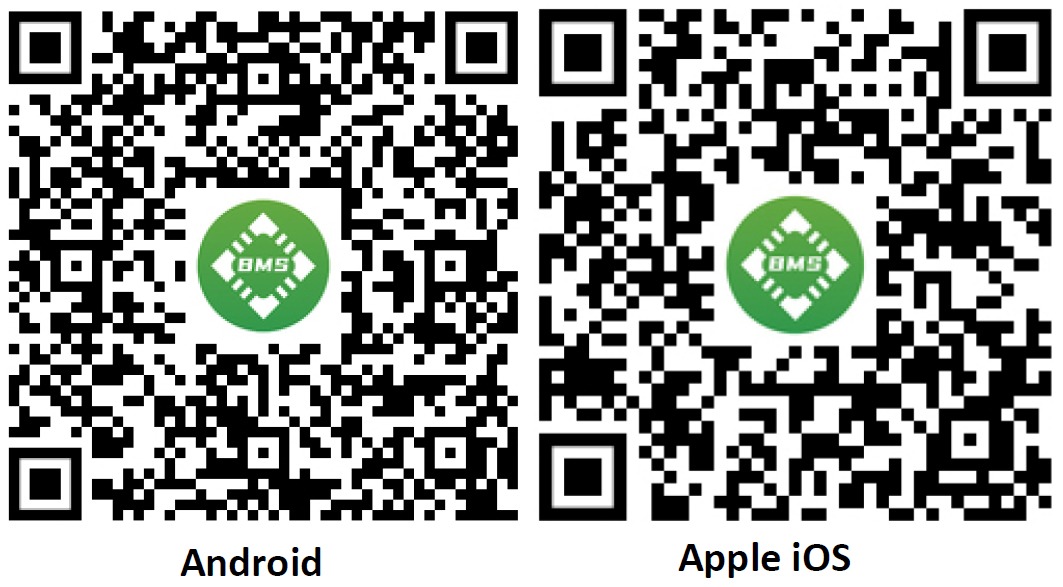
Intelligent management of energy transfer between battery cells and protection against premature damage. The Daly balancer communicates via UART, RS485, or Bluetooth. Use it to enhance the performance and stability of the cells. Suitable for lithium batteries LiFePO4. To communicate via Bluetooth, download the SMART BMS app for Android, or the SMART BMS app from the Apple Store, or PC software.
You can also use the QR code to download the app.
Balancing current: 0~1A. Suitable for 3-24s LiFePO4 batteries. Compatible with other BMS brands. The DALY active balancer is applied in energy storage systems using lithium batteries, such as e-bikes, electromobility, outdoor and indoor energy storage.
|
Used for connecting to a Bluetooth app on external software (tablet, mobile). Length: 45cm. |
|
|
NTC |
Fast response and stable performance over a long period. With NTC, you can monitor the battery temperature through the app. Length: 25cm. |
|
Communication Cable |
Wire harness with lugs for easy connection and prevention of disconnection. Length 30cm (3~6s), 35cm (7s), 45cm (8~24s, ≤100A), 60cm (3~24s, ≥120A). |
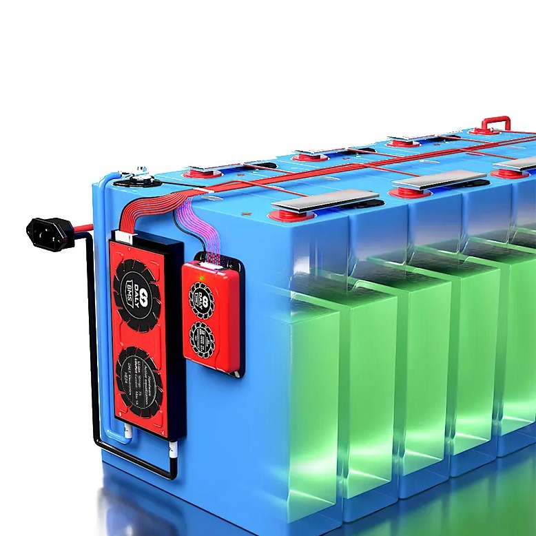
Sequence of connecting BMS to the battery:
Make sure to use appropriate twisted wires with correct cross-section; B- and P- should have different colors. Pay attention to the markings of the B and P poles.
After completing the wiring:
Connection of the active balancer
※ The active balancer must match the BMS with the same string count/number (S). Different S numbers cannot be combined.
Device - DALY SMART Balancer Active 8S for balancing cell voltage and monitoring energy transfer among them.
ATTENTION! THIS BALANCER HAS NO BMS FUNCTION. THIS PRODUCT ONLY EXTENDS THE FUNCTIONALITY OF CURRENT BMS.
*Product photo is illustrative
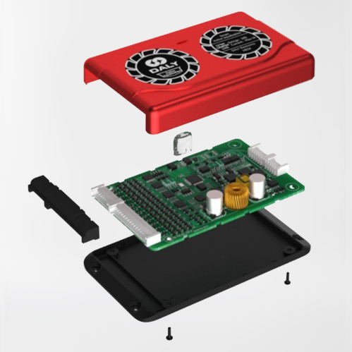
Accessory - The DALY Bluetooth module for connecting your Smart BMS and balancers with an application on your smartphone. Once connected, you can monitor real-time battery information such as voltage, temperature, power, charging, discharging, etc.
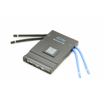
Smart Active Balance BMS from JIKONG. For 4S to 8S LiFePO4 or Li-Ion batteries. BMS 100A / balance current 0.6A, with integrated Bluetooth for communication with mobile app.
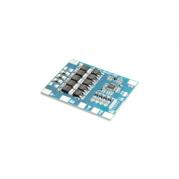
BMS 20A with active balancer 0,6A for 4S LiFePO4 batteries type 18650.
Accessory - The DALY Bluetooth module for connecting your Smart BMS and balancers with an application on your smartphone. Once connected, you can monitor real-time battery information such as voltage, temperature, power, charging, discharging, etc.
Smart Active Balance BMS from JIKONG. For 8S to 24S LiFePO4 or Li-Ion batteries. BMS 60A / balance current 0.6A, with integrated Bluetooth for communication with mobile app.
Smart Active Balance BMS from JIKONG. For 4S to 8S LiFePO4 or Li-Ion batteries. BMS 100A / balance current 0.6A, with integrated Bluetooth for communication with mobile app.
This BMS with active balancer, the JIKONG 8S-20S 200A, is a premium control system for high capacity LiFEPO4, Li-Ion, LTO batteries. It is compact, easy to use via Bluetooth (built-in) via mobile app (Android, iOS). It monitors battery status, allows adjustment of discharge and charge parameters. Suitable for use in electromobility, backup power sources, solar power plants or energy storage systems.
Do not forget to order an RS485 converter to ensure the necessary data communication.
*Product photo is illustrative
This BMS with active balancer, the JIKONG S-24 150A, is a premium control system for high capacity LiFEPO4, Li-Ion, LTO batteries. It is compact, easy to use via Bluetooth (built-in) via mobile app (Android, iOS). It monitors battery status, allows adjustment of discharge and charge parameters. Suitable for use in electromobility, backup power sources, solar power plants or energy storage systems.
Do not forget to order an RS485 converter to ensure the necessary data communication.
*Product photo is illustrative
BMS 10A with active balancer 0,6A for 4S LiFePO4 batteries type 18650.